
Spring Columns for CCGA Packages – High-Reliability BGA Replacement for Aerospace & Defense
In many high-reliability electronic systems, the first thing to fail is not the chip, but the joints that connect it to the PCB. Large ceramic BGA packages are especially vulnerable: under wide temperature swings, continuous vibration and mechanical shock, solder balls can crack and cause intermittent or permanent open circuits.
For aerospace, defense, energy and industrial projects, that failure risk is simply not acceptable. This is why more design teams are turning to spring columns for Ceramic Column Grid Array (CCGA) packages as a long-term, robust interconnect solution.

1. Why Standard BGA Solder Balls Reach Their Limits
BGA solder balls are an excellent choice for many consumer and industrial products. They are compact, easy to assemble and cost-effective. However, they have a structural limitation that becomes obvious in harsh environments:
- Large ceramic packages expand and contract differently from FR-4 or high-Tg PCBs
- Wide temperature cycling (for example from –55 °C to +125 °C) causes repeated expansion and contraction
- Vibration and mechanical shock add extra mechanical stress
Because BGA balls are short and relatively stiff, most of the strain is concentrated at the narrow region where the ball meets the pad. Over time, this area is prone to fatigue cracking, especially in the outer rows of a large package.
CCGA technology was introduced to address this problem by replacing balls with taller solder columns. The greater height provides more flexibility and spreads stress along the whole column. Even so, in the most demanding applications, even solid solder columns may not provide enough margin. That is the gap spring columns are designed to fill.
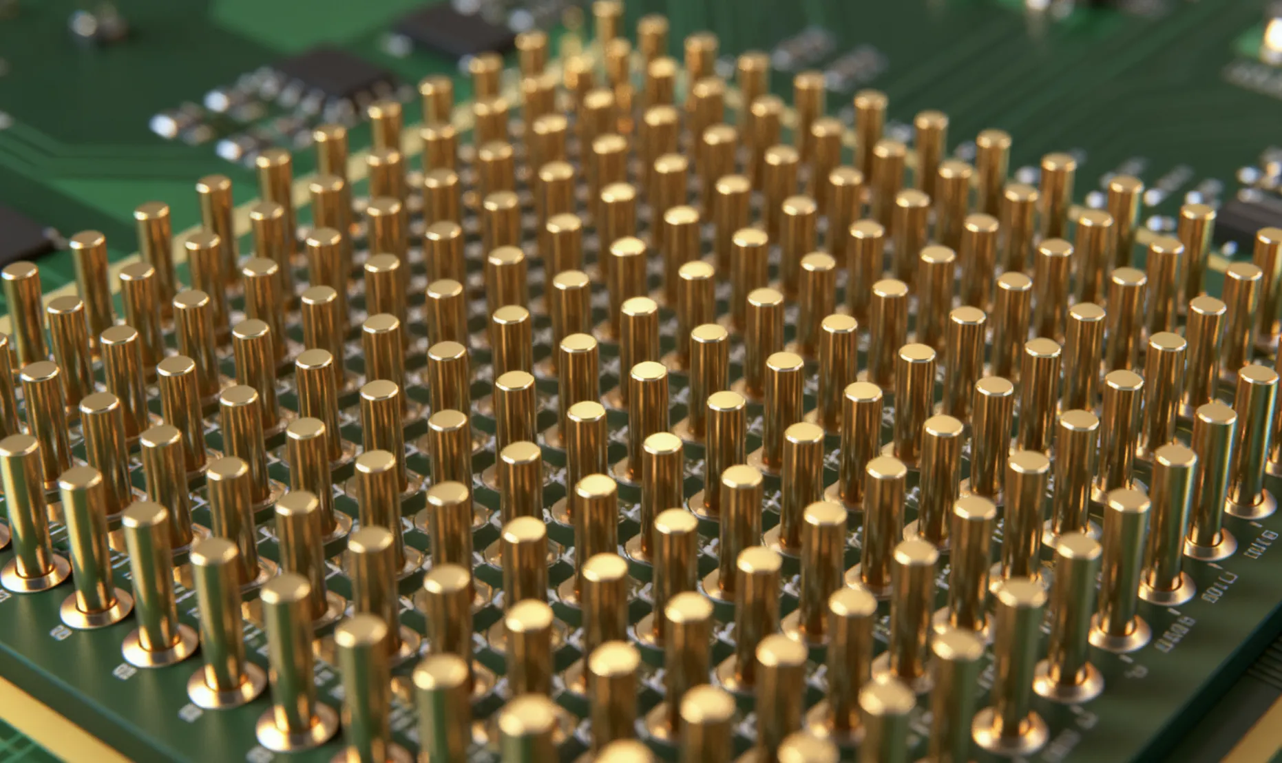
2. What Is a Spring Column?
A spring column is an advanced CCGA interconnect that incorporates a spring-like structure rather than relying on a solid slug of solder.
Typically, a spring column includes:
- A compliant metal spring (often a micro-coil or similar structure)
- Solderable terminations at both ends to connect to the ceramic package and the PCB
- Precisely controlled height and diameter suited to the package pitch and pad design
Instead of behaving like a rigid pillar, the spring column can bend and compress. It behaves like a miniature suspension system at each contact point, absorbing relative movement between the package and PCB.
Key technical characteristics designers focus on include:
- Column height (often in the range of about 1.5–3.0 mm, depending on pitch and package size)
- Column diameter (matched to pad size and pitch, for example around 0.25–0.50 mm)
- Alloy system (lead-bearing or lead-free, depending on regulations and reliability strategy)
- Plating and surface finish (tin-lead, nickel/gold, etc. to match the assembly process)
3. How Spring Columns Improve Reliability
3.1 Thermal cycling and CTE mismatch
In high-reliability sectors, boards are typically subjected to many hundreds or even thousands of temperature cycles over the product’s life. The difference in coefficient of thermal expansion between a ceramic package and the PCB creates significant shear strain at each interconnect.
With BGA balls or solid columns, this strain concentrates at the solder interfaces. With spring columns, part of that strain is absorbed by the spring geometry:
- The coil flexes as the package and PCB move differently
- Stress is distributed along the length of the column instead of being focused in a thin solder fillet
- The risk of fatigue cracking at the interfaces is reduced
The result is a substantial increase in solder joint life under aggressive thermal cycling.
3.2 Vibration and mechanical shock
Systems in aircraft, launch vehicles, armored vehicles, offshore platforms and heavy industrial equipment all experience strong vibration and occasional high-g shocks.
Rigid interconnects transmit most of that energy into the solder joints and package terminations. In contrast, spring columns:
- Act as mechanical dampers at each I/O
- Deflect under load and absorb part of the shock energy
- Reduce peak stresses in the solder interfaces
For applications where boards must survive random vibration profiles and severe shock levels, this extra margin can be crucial.
3.3 Electrical and signal performance
Spring columns are also part of the electrical path between chip and board. High-quality designs aim for:
- Controlled impedance suitable for high-speed digital buses and RF lines
- Low inductance and good current-carrying capability for power pins
- Consistent electrical behavior across thousands of interconnects in one package
When correctly specified and integrated, spring columns provide both mechanical compliance and stable electrical performance.
4. Where Spring Columns Make the Biggest Difference
Spring columns are not intended for low-cost consumer goods. They are designed for boards where reliability expectations are extremely high and access for rework is limited or impossible.
Typical use cases include:
Aerospace and satellites
- On-board computers and payload processors
- Power conditioning and distribution modules
- Telemetry and communication units
Equipment must endure launch vibration, vacuum, radiation and wide temperature swings with no opportunity for repair once in orbit.
Defense and avionics
- Guidance and navigation systems
- Radar and electronic warfare processing modules
- Flight control computers and engine monitoring units
Here, long service life, continuous vibration and strict safety requirements make long-life interconnects essential.
Rail, energy and heavy industry
- Traction inverters and braking control systems
- Substation and grid control electronics
- Offshore platforms and down-hole tools
These applications experience continuous operation, harsh environments and high downtime costs. A single board-level failure can have serious operational and financial consequences.
When the cost of failure far outweighs the incremental cost of a more advanced interconnect, spring columns are a strong candidate.
5. Key Parameters to Define Before Sourcing Spring Columns
To evaluate spring columns effectively and get accurate proposals from suppliers, technical and purchasing teams should align on a set of core parameters before sending an RFQ.
5.1 Package and PCB information
Gather and share:
- Package type (CCGA, LGA or similar)
- Package body size and thickness
- Pitch and I/O count
- Land pattern drawings for both package and PCB
- PCB material, thickness and expected warpage limits
This information drives the recommended column height, stiffness and coplanarity requirements.
5.2 Column geometry
Decide or request guidance on:
- Target column height after soldering
- Column diameter suitable for the pad and pitch
- Spring structure type, if there are options (e.g. micro-coil vs. other compliant structures)
- Coplanarity tolerance for the array
A taller column generally increases mechanical compliance, but the design must also fit standoff height constraints and electrical requirements.
5.3 Alloy and plating
Clarify:
- Whether the project requires lead-bearing or lead-free interconnects
- Preferred alloy families (for example traditional tin-lead vs. advanced lead-free solders)
- Required plating systems and finishes
- Applicable regulations and exemptions
Clear decisions here help avoid issues later in qualification and compliance reviews.
5.4 Reliability and test profile
Define realistic qualification and acceptance criteria:
- Thermal cycling range, number of cycles, dwell times and ramp rates
- Vibration profiles and shock levels the assembly must survive
- Inspection methods and acceptance limits (X-ray, cross-sections, shear testing, etc.)
Sharing this information allows potential suppliers to suggest column designs and alloys with adequate margin for the intended environment.
6. A Practical RFQ Checklist for Spring Columns
When you are ready to request a quotation, structuring the RFQ clearly saves time on both sides. A practical checklist could include:
- Project overview
- Application type and environment
- Mission life and any special constraints (for example no access for rework)
- Technical drawings and data
- Package mechanical drawing with pad layout
- PCB land pattern and stack-up summary
- Any height restrictions or keep-out areas
- Interconnect requirements
- Desired spring column height and diameter (if known)
- Alloy and plating preferences
- Lead-free or lead-bearing policy
- Reliability expectations
- Target thermal cycling profile
- Vibration and shock requirements
- Relevant internal or external standards
- Commercial information
- Annual volume expectations and lot sizes
- Preferred packaging formats
- Target delivery schedules or critical milestones
With this level of detail, suppliers can quickly assess feasibility, propose suitable spring column configurations and provide realistic pricing and lead times.
7. When a Spring Column Upgrade Is Worth It
Upgrading from BGA balls or standard CCGA columns to spring columns is a strategic decision. It becomes a compelling option when:
- Qualification tests reveal solder fatigue or intermittent opens on large ceramic packages
- The application is moving into a harsher environment than originally planned
- Mission life requirements increase significantly
- Access for rework is very limited or impossible
In these cases, spring columns can transform the interconnect from a known weak point into a robust part of the design, reducing risk and avoiding expensive redesigns later.
8. Turning Interconnects into a Reliability Asset
As operating conditions and reliability demands become more severe, interconnects can no longer be treated as an afterthought. For large, high-value packages in harsh environments, spring column CCGA gives design teams an option that combines:
- Long-life performance under thermal cycling
- Superior resistance to vibration and mechanical shock
- Stable electrical characteristics for high-speed and high-power applications
For engineering and purchasing teams responsible for critical hardware, evaluating spring columns early in the design process is a practical move: it helps ensure that the connection between the chip and the board is no longer the first thing to fail, but a deliberate strength of the overall system.